Overlapping photographs are the foundation of reliable drone maps, but simply taking many images does not guarantee an accurate result. The real work happens when specialized software identifies shared features, calculates camera positions and turns thousands of pixels into a consistent, measurable model of the ground.
In drone mapping, each photograph records only part of a scene from a particular angle. Carefully planned Image overlap gives processing software the repeated visual information it needs to connect those views, while ground measurements help align the finished map with real-world coordinates. The resulting products can include an Orthomosaic, a Point cloud or a three-dimensional surface model.
Capturing overlapping aerial images for drone mapping
Reliable reconstruction begins in the air. A drone follows a planned route and captures Aerial imagery at regular intervals, with each photograph sharing part of its scene with neighboring images. That shared ground allows software to recognize the same features from different viewpoints.
The required overlap depends on the terrain, camera angle, flight height and mapping objective. Flat, open ground may be relatively straightforward to photograph, whereas buildings, trees or steep slopes can hide surfaces and create gaps. A crosshatch flight pattern, with additional passes at a different direction, can help capture complex structures from more viewpoints.
Before processing begins, image sets are checked for blur, exposure problems and missing coverage. Overlap is useful only when the shared details are sharp and distinctive enough to match.
Matching features through photogrammetry
Once images are collected, software searches for recognizable visual details—such as corners, texture patterns or the edges of a roof—and identifies where they appear in multiple frames. The processing stage uses these correspondences to estimate camera positions and the relative shape of the photographed scene.
Two connected techniques explain much of this transformation:
Building geometry with Structure from Motion
Structure from Motion (SfM) compares matching features across photographs to estimate both camera locations and a preliminary three-dimensional arrangement of the scene. As the system links more images, it refines those estimates into a coherent network of camera positions and observed points.
This is an iterative process: weak or inconsistent matches can distort the geometry, so processing tools identify outliers and adjust the model. The quality of the result depends on more than the number of photographs; clear detail, strong overlap and varied viewing angles all help constrain the reconstruction.
Creating a dense point cloud and 3D reconstruction
After the camera geometry is established, the software can compare image details in greater depth to calculate a dense Point cloud. Each point represents an estimated position on a visible surface, and together the points describe terrain, structures and other features. This is the basis of a 3D reconstruction, sometimes described as the D reconstruction stage in a mapping workflow.
The point cloud can support further products, including elevation models and textured surface models. Yet it represents only what the camera could see; occluded areas and featureless surfaces may remain less reliable.
Georeferencing models with ground control points
A model can be internally consistent and still be misplaced, rotated or scaled incorrectly in relation to the Earth. Georeferencing connects the reconstructed scene to a real-world coordinate system, making its positions and measurements meaningful beyond the image set itself.
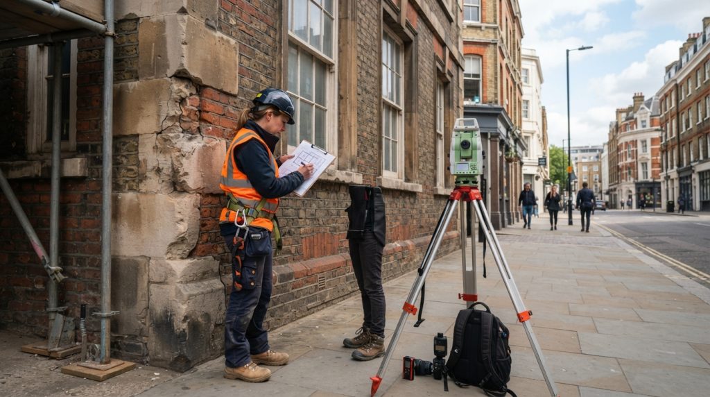
Ground control points are identifiable locations measured independently on the ground, then marked in the corresponding photographs. The processing software uses them to anchor the model and assess how closely its calculated positions match surveyed coordinates. Their distribution matters: points spread across the site and, where appropriate, at different elevations can reveal errors that clustered points might miss.
Independent check points, which are not used to adjust the model, provide a separate test of positional accuracy. This distinction helps show whether the result is genuinely well aligned rather than merely fitted to its control measurements.
Delivering orthomosaics and dependable mapping results
With image alignment and georeferencing complete, the software can combine corrected photographs into an Orthomosaic. Unlike a collection of ordinary aerial photographs, this map compensates for perspective and terrain-related displacement, allowing features to be viewed consistently from above.
Different outputs serve different purposes, so the product should match the task. The following comparison summarizes common deliverables and what each one can reveal:
| Output | What it represents | Typical use |
|---|---|---|
| Orthomosaic | A geometrically corrected, map-like image | Visual inspection and measuring horizontal features |
| Point cloud | A set of three-dimensional surface points | Examining terrain, structures and surface shape |
| Elevation model | Height values arranged across an area | Studying slopes, drainage and changes in relief |
When each stage is planned and checked, overlapping photographs become more than a visual record: they form a measurable representation of the landscape. For project-specific accuracy requirements or complex sites, consulting a qualified surveying or photogrammetry professional can help determine the right workflow.